| Image may be NSFW. Clik here to view.  |
| Temperature Controlled DC motor |
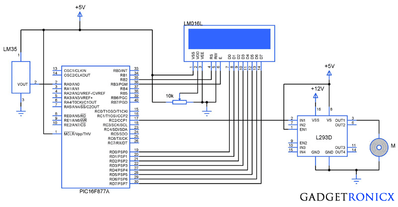
You might have come across several applications where we need to control a specific device based on analog parameter. This Embedded system works in a similar concept where we are about to control the speed of a DC motor using based on the external temperature. The rise in temperature will result in increase in speed of the motor and vice versa. These type of systems can generally be used to maintain temperature of a room or object automatically.
DESIGN:
- The temperature is measured by means of a temperature sensor LM35.
- The output voltage of the sensor is fed to the A/D channel of the Microcontroller.
- Based on the sensed temperature the speed of the motor is controlled using PWM .
- Several temperature ranges was set in the code to vary the motor speed based on the level of temperature sensed.
- The speed of the motor is controlled by using PWM.
- The motor is driven using a driver IC l293D, See a brief explanation on its working and wiring here
LM35:
| Image may be NSFW. Clik here to view.  |
| LM35 Pin Diagram |
Lm 35 is used to sense the external temperature which is capable of sensing temperature ranges from -55 to 150 C. The output voltage is proportional to the temperature hence there is no need of trimmers to calibrate the reading. The output voltage of this sensor varies by 10mv per degree change in temperature.
CALIBRATION:
We are using a 10 bit ADC and Vcc as Vref to the ADC module of the Controller. So in order to determine the step size we have to divide the Vref by our resolution that is 2^10 ( 1024 ).
We obtain a change of 10mV with each rise or fall in temperature from the sensor. And value in the ADC register will alter by two steps with each degree change in the sensor since two increments of step size i.e 4.833mV * 2 = 9.96mV which is approximately equal to 10mV. So in order to obtain the original value we have to divide the contents in the ADC register by 2
Real value = ADC value / 2
CODE:
This code was built using CCS compiler for PIC Microcontrollers.
|
The above code uses built in functions in the CCS compiler to use the A/D and PWM feature in the Microcontroller. The received analog value is calibrated to display the temperature in the LCD. The "real_value" int value is converted to character using "sprintf" in order to display the temperature values.
The temperature ranges and duty cycle of the PWM is given using the subroutine ".motor". So the microcontroller runs a check on the temperature every time and alters the speed of the motor based on it.
Like this Project, share this with others through social sites and don't forget to follow us there for more of these.
Image may be NSFW.
Clik here to view.![]() Image may be NSFW.
Image may be NSFW.
Clik here to view.![]() Image may be NSFW.
Image may be NSFW.
Clik here to view.![]() Image may be NSFW.
Image may be NSFW.
Clik here to view.![]() Image may be NSFW.
Image may be NSFW.
Clik here to view.![]()
Image may be NSFW.Clik here to view.
Clik here to view.
Clik here to view.
Clik here to view.
Clik here to view.
Clik here to view.