Quantcast
Channel: Gadgetronicx
Viewing all 215 articles
Browse latest View live

QUIZ BUZZER CIRCUIT USING IC 74LS373

$
0
0
quiz-buzzer-circuit-ic-74ls373-electronic
Quiz buzzer circuits have been available numerous in number yet we face many problems in most of the circuits and some cost much. Here is a perfect and cost effective electronic circuit which can be used for quiz in schools and colleges.This circuit works with special IC known as IC 74LS373, switches, Piezo buzzer and bulbs for the indication.The switches are given to each participating competitors and the respective bulbs can be placed before them to determine which team pressed the switch first. Lets look into the working of this quiz buzzer circuit.

WORKING:
IC 74LS373 forms the main heart of this circuit and it was a transparent latch which consists of a eight latches with three state outputs. This IC takes eight inputs enabling eight teams to play with it.The brief working explanation of the IC was given in this article Working of IC 74LS373. The circuit was powered with 5V power supply and as you can see that the switches were connected directly to the power supply so when the switch is not pressed it gives low signal to the input pins (D0-D7).

SCR(Silicon Controlled rectifier) was connected to the output pins of the IC and along with it diodes are also connected. SCR was used here in order to switch  ON the bulbs which require considerably large amount of power. And diodes was used to allow the forward flow of current from the output pins of the IC and thereby switching the transistor ON and thus perform the Latching operation.

Quiz buzzer circuit can be initialized by switching ON the power supply and once it was ON the quiz buzzer will be ready to use.When any of the input switches from (S1-S8) was pressed, then the respective output pins will go high this induce the transistor to switch ON and then the  LE pin was pulled to low state.This low state in the LE pin enables the latch of the IC thereby providing continuous high signal in the output pin. In this point of time the IC will not respond to any of the input signal given by any other switches to it. And the high output signal further switches the SCR on and thereby the respective bulb of the team will glow and also the transistor T1 connected to the Buzzer will switch the buzzer ON. Since the output was latched with the input this circuit eliminate the confusion among the participants and also it provides room for eight teams to play at a time.

This Buzzer circuit can be reset by switching the power supply OFF and turning it ON again. So this quiz buzzer circuit was cost effective and efficient comparing to other circuits. It will be a great mini project to do at you home and i bet you will like it. Post your queries and comments regarding this circuit and i am happy to help you.

I hope this circuit helps you and enhance your knowledge about Electronic circuits.Share this post through social networking sites and help others. And do follow us through Email and social sites to enable our posts reach you.Thank you and have a great day ahead.

SCENTEE: CONVERT SMARTPHONE NOTIFICATIONS TO PLEASANT FRAGRANCE

$
0
0


Smartphones have many ways to display notifications alert and it has been evolving every day with the new upcoming phones in the market. In addition to this "Scentee" a round, plug-in smartphone accessory that emits fragrances and customizable LED lighting when promoted  by a complementary mobile app. This provides complete new notification alert experience for the user by spreading pleasant fragrance in the air and also comes in variety of fragrances. This gadget was compatible with both iOS and Android smartphones, can be attached through device's headphone socket.
 
The Japanese company Chatperf have introduced this new accessory to give a complete new experience with the notifications alert. The next time you get a Facebook Like, you can smell something like strawberry, mint or other flavors of your wish. This small accessory disperses scents from a small liquid capsules loaded into it. An application compatible to iOS and Android was used to configure the when the devices releases its scent.

This cartridge can yield about 100 sprays, each costs about $5 and it is about to be launched on November 15 in Japan. The company also planned to produce cartridges of many other flavors. I personally think this was not a great way to indicate notifications but still it was quite a great innovation. And it certainly indicate that interaction of user with gadgets of modern world have been enhancing greatly. Good or bad Scentee marks a new era of notifications alert.

Hope you like this post don't forget to share this post with others. Post your opinions and if you got something to add in this story share it in the comments below.


ROUNDED SOCIAL ICONS WITH SPINNING HOVER EFFECT USING CSS AND HTML

$
0
0
Rounded-social-icons-widget-html-css
Image hover effects have been quite an asset to a site as it gains visitors attention and also make your site more attractive. You might have seen these kind of effects used in social media buttons in several sites to draw the audience to follow them through it. This post narrates you about a similar kind of spinning social icons hover effect using simple HTML and CSS codes. You can view the demo of this effect at the right hand top in my site. Using rounded social icons for this effect make it more attractive and this effect can be done in two ways.


1)SINGLE SPIN: In this effect the image will spin only once on mouse hover and it will not return to the original position after the mouse is out.
    2) DOUBLE SPIN: In this effect the image will spin twice, the first spin will be when the image is hovered and the image will spin back to its original position when the mouse is out.
    CSS CODE:

    SINGLE SPIN:

    1. #spin1 img:hover{
    2.      -webkit-transition: all 0.6s ease-in-out;
    3.      -moz-transition: all 0.6s ease-in-out;
    4.      -o-transition: all 0.6s ease-in-out;
    5.      -ms-transition: all 0.6s ease-in-out;
    6.       transition: all 0.6s ease-in-out;
    7.      -webkit-transform: rotate(360deg);
    8.      -o-transform: rotate(360deg);
    9.      -moz-transform: rotate(360deg);
    10.      -ms-transform: rotate(360deg);
    11.      transform: rotate(360deg);
    12.                              }
    In this spin1 hover effect as you can notice we are using rotate property to spin the image up to our desired angle. I have given the rotate value as 360deg so that the icon can complete a full rotation. You can rotate the image either clockwise or anticlockwise manner. The degree values should be positive (360deg) for clockwise rotation and (-360deg) for anticlockwise rotation.Moreover in this above code the whole code was assigned under the hover condition of the image and therefore the image will undergo one rotation only. 
      

    DOUBLE SPIN:

    1. #spin2 img{
    2.      -webkit-transition: all 0.6s ease-in-out;
    3.      -moz-transition: all 0.6s ease-in-out;
    4.      -o-transition: all 0.6s ease-in-out;
    5.      -ms-transition: all 0.6s ease-in-out;
    6.      transition: all 0.6s ease-in-out;
    7.                  }
    8. #spin2 img:hover{
    9.      -webkit-transform: rotate(360deg);
    10.      -o-transform: rotate(360deg);
    11.      -moz-transform: rotate(360deg);
    12.      -ms-transform: rotate(360deg);
    13.      transform: rotate(360deg);
    14.                               }
    In this spin2 hover effect the hover and the image properties was assigned separately so that the image will undergo rotation when the mouse is hovered on the image. And the image will return to its original position by taking another rotation after the mouse is out from the image. The transition time 0.6 denotes how fast the image transition will be, you can change the value to achieve fast or slow transition of your desire.

    HTML CODE:
    1. <div id="spin2">
    2. <p style="border-radius:10px 10px 10px 10px;border:5px solid black;width:420px;">
    3. <a href="Your social profile URL1">
    4. <img src="Your image URL1"> </img> </a>
    5. <a href="Your social profile URL2">
    6. <img src="Your image URL2"> </img> </a>
    7. <a href="Your social profile URL3">
    8. <img src="Your image URL3"> <img> </a>
    9. <a href="Your social profile URL4"> 
    10. <img src="Your image URL4"> </img> </a>
    11. </p>
    12. </div>
    The HTML part of this effect was very easy to implement, all you have to do is place the image either in a <div> tag with id either spin1 or spin2. You can also place the image inside the <p> tag with the id spin1 or spin2. I have added some styling properties for <p> tag to make it more attractive to make it look like a widget. Now replace all the "profile" and "image URL's" in the above code with your respective URL's and now your widget is ready.
    I hope you this post was useful to all of you for more of image hover effects jump to our HTML/CSS codes page. Share this post with others through social sites if you like it and thank you for visiting, visit again.


    INFOGRAPHICS: FASCINATING SMARTPHONE STATISTICS

    $
    0
    0
    smartphone-statistics

    Smartphones becomes a part of our daily life and its almost a thing which many of us cannot live without. This post brings you statistics about the smartphones and its users around the world with cool infograph representation produced by Coupon Audit( Provides Zappos Coupon code) and Gadgetronicx.


    Smartphone-Statistics-infograph-users-shares

    Educate your audience by placing this Embed code in your site.


    Hope this was very informative to you. Share this Infographics with others through social networks if you like it.Thank you for visiting us and come back again. 

    DUAL INPUT BATTERY CHARGER CIRCUIT

    $
    0
    0
    two-voltage-range-battery-charger-circuit
    Battery chargers circuit play quite a important role in everyday life as we use variety of chargers and most of the chargers we avail from the market are quite expensive. So this circuit teaches you how to make one with same efficiency and reliability we obtain from those chargers. The above circuit was designed to give two different kinds of voltages as output and based on our requirements we can select one. As you can notice one part of the circuit works with input AC voltage other with input DC voltage.

    WORKING:
    The first part of the circuit is powered by step down transformer which converts the 230V AC into 9V. It was then fed into the bridge rectifier to convert it from AC voltage to DC voltage. Then the rectified voltage was directly fed to the output through some LED's for the purpose of indication. The LED2 was used to indicate the Power ON and LED3 to indicate the charging( Battery was connected to the charging end). The current limiting resistor R2 was added to limit the current flow and voltage obtained from the output will be around 7.2V.


    The second part of this circuit was powered by external DC power supply, where resistor R4 limits the input current to a safe value after fed into the polarity protection diode D5. Then it was fed into the IC1 7805 which gives 5V as output from the 3rd pin. A LED1 was connected through the com pin of the IC1 and it indicates that external DC power supply was used. The 5V was then connected to the output through some LED's and resistors to limit the current value obtained from the 7805. The output voltage obtained from this part will be around 3.8V as most of the mobile batteries use 3.7-4.6V as input, this is well suited to charge up your mobile with ease. Heat sink is recommended as this type of circuits will be used for long time and produces high heat while powered ON.
    LM7805-7805-pin-diagram-description
    You can add up any voltage regulators and resistors to limit the voltage value obtained at the output. Usage of Variable resistors allow you to utilize this circuit for wide range of voltage requirements by the battery. This two voltage range battery charger circuit provides  room to either use AC or DC supply as input. 

    Hope this circuit will be useful to all of you.Share this circuit with your friends through social sites  if you like it. And don't forget checkout our exclusive  Electronics page for wide variety of circuits.Thank you keep visiting us.

    LG G FLEX : FLEXIBLE AND SELF HEALING SMARTPHONE

    $
    0
    0
    LG-G-Flex-Flexible-smartphone
    Smartphones has been evolving day to day with their size, look, specifications and performance. And flexible phones have become quite a great evolution in the smartphones with series of flexible smartphones already released LG has come up its flexible smartphone LG G Flex launched earlier this month. This super smartphone was announced after LG successfully developed  flexible smartphone batteries. So what makes this smartphones so special?, there is lots of cool features in this smartphone to talk about and pick our favorite among it. Coolest of it all was the rear finish which was said to be "Self Healing" derived from paint finishes in the Automotive industries. The surface will expand after being scratched and seals up any damage, preserving the phone's classy look. Lets look into the complete features and specifications of this LG G Flex Smartphone.


    FEATURES AND SPECIFICATIONS:
    • This device features a 6 inch OLED display which has a 1280 x 720 pixel resolution.
    • A vertical curve in the display seems to provide a clear and glar-free videos and the display is flexible to some extent, can be easily placed in the pants.
    • The device was powered by a 2.26 GHz quad-core Snapdragon 800 processor CPU and a 450 Mhz Adreno 330 GPU for Ultrasmooth gameplay.
    • It carries a 13 Megapixel  rear facing camera and a 2.1 Megapixel front facing camera which was pretty normal like other smartphones.
    • Build with 2GB RAM, 32GB of internal storage it doesn't support external memory which i see as a small disadvantage.
    • It runs in Android 4.2.2 Jelly Bean with LTE enabled and NFC is also added which was quite missed out one in most of the latest devices.
    • G Flex houses its key control buttons on its back, just like G2 and featuring a new "KnockOn" functionality which allows user to wake up handset with tapping the screen twice.
    • There is also a new Urgent call alert which sends alert through a LED flashing, when user miss several calls in a row from the same number.
    • And swing Lock screen which changes the lock screen image depending on how you hold the phone.
    • A unique rear finish which enables the phone to heal after facing a scratch and it was claimed to "Self healing Feature"
    This device is quite on a high with lots of cool features but a slight drawback with its memory. Currently Curved and Flexible smartphones started to fill the market and this device from LG seems to stand out among all due to its uniqueness.

    Share this post with your friends through social networks if you like this post. Check into our site for more of posts about gadgets. Thank you for visiting and do visit again

    XBOX ONE VS PLAYSTATION 4: BATTLE FOR BEST GAMING CONSOLE

    $
    0
    0
    Battle-of gaming-console-Xbox-one-vs-Playstation-4-PS4
    Sony's PlayStation 4 locked horns with Microsoft's Xbox One for the battle of best next generation gaming console. These two rivals have been competing in the gaming world ever since Microsoft releases its own gaming console Xbox. The two giants have released their next generation gaming console Xbox One and PlayStation 4 at same month, this adds spice to their competition. Both the consoles have already reported to sold one million units, but still its pretty hard to find which was the best console and what makes it best. So here is some of the comparisons between these two consoles which can make a difference in this battle of Gaming consoles.

    HARDWARE:
    The Xbox One and the PlayStation 4 have similar type of hardware. Both the consoles are built on eight-core-processor. However the Xbox One was powered by 1.75 GHz custom CPU while PS4 uses 1.6 GHz AMD "Jaguar" processor. So both the consoles will do a great job when comes to multitasking. So it wont create any imminent difference between these consoles.

    But Playstation 4 surpasses Xbox One with a more powerful   GPU. Meanwhile Xbox One reserves  about 10 percent of the GPU power for Kinect. Both have 8GB RAM,but the PlayStation 4 uses a powerful version.

    Looking at some of the third party games, the PS4 will run them at 1080P while Xbox One run them at only 720p. So when comparing the graphics power Sony's PlayStation 4 has the upper hand.

    STORAGE:
    Both consoles have identical sized hard drives of 500 GB and that offers a great space to save games and install apps. Both the consoles require to install the games in the hardware thereby eating some storage. We don't get the facility of playing the game just by ditching the disc in the drive.

    The Xbox One allows external storage through a USB whereas PS4 has an upgradable hard drive, which provides room to add up memory for future use. So in storage also Sony holds a slight advantage than the Microsoft's console.

    MOTION:
    The Microsoft Kinect was updated and is far superior than its predecessor. Not only the camera is high definition, but it also works better in smaller rooms and can perform well in the dark. It is sensitive enough to capture pulse off your face, which is extremely impressive.

    The PlayStation has its own accessory Eye Camera and it performs a pretty decent job in the console. But the Sony's Eye lacks the fire power of the Kinect in the Xbox console. PS4 also tracks the players through new dual shock controller, similar to how move controllers and the eye camera work together. Voice recognition also added within the peripheral, so you can find games and apps on the playStation easily. So in this motion feature of the consoles Xbox one have the upper hand even though Sony brings good features with it.

    ENTERTAINMENT:
    The consoles are evenly matched when considering the entertainment features. The both consoles play Blu-Ray DVD's and they are almost silent while running which is major bonus for all the users. Both offer their own version of a music streaming service; both allow you to use services such as Netflix. So therby these two consoles are matched in Entertainment point of view.

    CONCLUSION:
    Its Pretty hard to say that which one was the best console with both having its own unique features. But both these consoles are made to take the gaming experience to the next level and both did perfect job they are assigned to. These two consoles can be a perfect gift for the Christmas to the hardcore gamers.

    Share this post with others through social networking sites and don't forget to stay connected with us through social networks and through Email subscription. Thank you for visiting Come back Again.

    SONY COMING UP WITH NEW WEARABLE TECH: SMARTWIG

    $
    0
    0
    Sony-Wearable-SmartWig-Wearable-tech-gadgets
    Wearable technology and gadgets have been coming out in several forms such as watches, Bands, T-shirts and lots more. Leading companies like Google, Samsung have already launched their wearable gadgets such as Google Glass , Samsung Gear in attempt to provide new way of interaction and smart computing to the users. Moreover this area was seen as trending one by all leading tech & Gadget companies since the need of integrating technology with humans is really high in the upcoming era. Keeping this in mind Sony has come up with its idea of new wearable tech known as "SmartWig" and has filed a patent application for it. The Japanese giant is looking to take the lead in the wearable technology sector against its rivals Google, Samsung which are already showing promising results with their wearable gadgets.


    SMARTWIG POTENTIAL USES:
    According to Sony, the wig could be made from horse hair, Human hair, Wool, Feathers, Yak hair, Buffalo hair or any kind of synthetic material. The communication interface and sensors placed in the wig are covered by parts of the wig in order to be hidden from others sight during use. A further potential improvement in this wig may use Ultrasound waves to detect the objects around the user.

    It can also be used in the healthcare sector as a combination of sensors that can help collect information such as temperature, pulse and blood pressure of the wearer. The data collected can be transmitted to the server computer ,thereby the conditions of the wearer can be monitored.

    Sony also listed various potential uses of this SmartWig including helping blind people to navigate roads. It also added that a small video camera or sensor on the wig could help to provide the position and location of the wearer. A remote user then use the image provided and send commands through the network to the navigation systems based on vibration motors integrated in this device. Thus this wig user can be manually guided to the desired destination.

    The device can also be used during presentations where a wearer can move to the next slide or previous one in the by simply raising his/her eyebrows. Sony also said that the SmartWig will be compatible with other devices such as glasses and smartphones.

    Its probably a great step by the Japanese giant to redeem its market in the wearable gadget sector which they have lost in the recent years, after their Smartwatches failed to create impact in the market. Sony also added that they had not decided on any plans for commercial production of the SmartWig and it was still under research.

    Like this post? Share it with your friends through social sites and comeback for more of the Technology and Gadget news.


    NEW INVENTION EXTRACT ELECTRICAL ENERGY FROM WIRELESS SIGNALS

    $
    0
    0
    Duke-engineers-device-electrical-energy-from-wireless-signals
    Energy demands have been increasing day by day and many companies have dedicated themselves to find a technology that can provide vast amount of energy to meet people demands. And that invention have finally arrived but not from any companies or organization but from hands of two Engineering students Alexander Katko (left) and Allen Hawkes. They invented a cheap device that collects stray microwave signals in the air and converts them into power for charging batteries. The device works similar to solar panels, the researchers claim that their converter can collect stray signals anything wireless, including satellite signals, sound or even Wi-Fi.


    The research team used fiberglass and copper energy conductors engineered to capture various forms of wave energy and tune them for useful applications. The researchers created a series of fiber glass and copper energy conductors on a circuit board, that converts microwaves into 7.3V of electrical energy. Hawkes one of the Engineer said that "We had been getting efficiency around 6 to 10%, but with this design we were able to dramatically improve energy conversion to 37% which is comparable to what achieved in solar cells."
    five-cell-metamaterial-array

    This was the five cell metamaterial array developed by the engineers and the beauty of this design is that the basic building blocks (metamaterial cell) are self contained and additive. So one can simply add more blocks to increase the electric power based on their needs. This device could be tuned for a multitude of frequencies to collect different types of energy including vibration and sound energy.

    The researchers further added that this power harvesting device could integrate into modern mobile phones, allowing it to recharge itself from the signal obtained through towers or satellites. So in a world were we are swimming in microwave signals, this device could provide a vast amount of energy which we need on daily basis. Imagine charging your smartphone through Wi-Fi signal or by means of stray signals from the Satellite overhead. This cheap and effective device could be a best solution to meet the energy needs of the world in our upcoming future.

    Share this post through social networking sites with your friends and feel free to comment your opinions or views about this post. Like our posts then don't forget to subscribe to our feeds, we will not spam promise.


    SEQUENTIAL DEVICE ACTIVATOR WITH TIME DELAY USING IC 555

    $
    0
    0
    sequential-process-control-timer-device-activator-ic-555
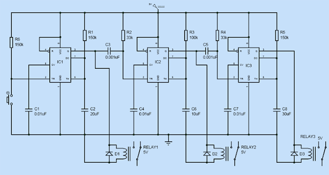
    Click here to see large resolution of  this circuit.            

    Sequential device activator or process control timer circuits have wide area of applications and its complexity varies depending upon the device to be activated. Here is a simple sequential device activator circuit using IC 555 and relay as activator. As we all know that IC 555 has some unique capabilities to act as a timer and oscillator. Here we employ the IC 555 as a timer to activate three device sequentially given specific timings for each device. The main advantage of this circuit is you can increase the number of devices to be activated just by increasing the count of 555 and you can vary the timings for each device activations. Its very important to understand the operation of IC 555 , so go through this  Working of IC 555 before moving to the next section of this Article.


    DESIGN:
    This sequential device activator was designed by means of three 555 IC's which are connected in sequential manner. The connected 555 IC's above are  working in Monostable mode of operation. The monostable mode operation is also known as single-shot since it generates pulse of specified width either high or low. And the above sequential activator was designed by connecting three monostable blocks together.
    monostable-mode-operation-ic-555
    The above given circuit illustrates the monostable operation of 555. This forms the basic building block of our activator circuit. In simple the monostable operation of IC 555 can be explained as whenever a positive trigger was given to the pin 2 of the IC, it will give a low output at pin 3. In case of a negative trigger a high signal ( logic 1) will be obtained at the output through pin 3. And the timing of the high pulse depends on the Resistor and Capacitor (RC) connected to the 6 & 7 pin of the IC. The timing can be obtained by using this formula.

    T= 1.1 x R x C

    By selecting the appropriate RC values using this equation we can achieve required timing for our activation.

    WORKING:
    The working of this sequential circuit was achieved by means of connecting the monostable mode circuits in sequence together. That is the output of the first IC will be fed as trigger to the 2nd pin of IC2. So when the 1st block was triggered to give high output, it goes as a positive trigger to pin 2 of the next IC. Since positive trigger was fed to the IC 2 we will obtain no output from it.

    When the output of IC1 goes from high to low, it gives a negative trigger to the 2nd pin of the IC2. As a result IC2 will be activated and the resultant high output will obtained at its pin 3. Then the process continues to the IC3 likewise many blocks can be added providing the optimum source to it.

    The timing of the high pulse or period of activation was given by the RC components connected to it.  The RC values connected to the blocks are IC1- 150k & 20uF, IC2- 100k & 10uF and IC3- 150k & 30uF. Therefore the timing produced by each blocks will be given  by

    T1 = 1.1 x 150k x 20uF = 3.3s
    T2 = 1.1 x 100k x 10uF = 1.1s
    T3 = 1.1 x 150k x 30uF = 4.5s

    These are the timing given to the devices in this sequential operation. And by varying the RC values, you can change the timing given by the IC to the relay or device. Then 5v Relay was connected directly to the pin3 of the 555 IC which in turn activate the device when the IC output was high. A protection diode 1N4004 was added along with it to avoid the spikes produced by the relay when it turned off suddenly. Thus we can achieve sequential device operation using IC 555 with specific timings for each devices.

    NOTE:
    When Relays higher than 5V range is used , its preferable to switch ON using transistor drawing supply directly from the source instead of  sourcing from the 555 IC.
    Share this circuit with others through social sites and feel free to comment if you have any queries or comments regarding this circuit. Also visit our Electronics Page to find large variety of useful circuits. Thank you for visiting our site and keep up the good work.

    SIMPLE IMAGE SLIDING HOVER EFFECT USING HTML AND CSS

    $
    0
    0
    katy-perry-wallpaper-cool-imagehover-effect-css
    Image hover effects have been  quite interesting to work and moreover it enhances the beauty  of websites when added at right places. You might have come across many types of Image hover effects created using simple HTML and CSS codes. You are about to see some similar kind of simple image hover effect using CSS here. The main concept behind this effect is we are going to place a background image which will be hidden by the image placed above it. When hovered the image in the above slides to reveal the background image. Sounds familiar, yeah all hover effects are connected well implementing methods usually differ. I have written many articles about image hover effects in this site before don't forget it in our HTML/CSS codes page.

    AFTER HOVERING:
    katy-perry-wallpaeper-image-hover-effect-css
    The above image illustrates the the sliding hover effect, how it reveals the image underneath creating a sliding effect. This hover effect works well with photo galleries and photography sites. The demo of this effect was added in this Demo effects page. Kindly consider that some of the effects in that page may not work due to blogger template, but i will assure it will work fine when you implement it separately. Lets move into the coding part of this effect.

    CSS CODE:
    1. .image{
    2.           padding: 0;
    3.           margin: 0;
    4.          -webkit-box-sizing: border-box;
                  }
    5. .slide {
    6.           background: url(Background Image URL)no-repeat; 
    7.           display: inline-block;
    8.           background-size: 400px 400px;
    9.           }
    10. .slide img{
    11.           -webkit-transition: all 1s ease-in-out;
    12.           -moz-transition: all 1s ease-in-out;
    13.           -o-transition: all 1s ease-in-out;
    14.            transition: all 1s ease-in-out;
    15.                 }
    16. .slide img:hover
    17.               {
    18.                 margin-left: 430px;
    19.                } 
    In the above code  i have added a background image and assigned size for it in order to match the image above it. The key element of this hover effect lies in line 18 as i increase the left margin by 430 pixels to reveal the background image. and some transitions to make this effect look cooler.  And when the mouse is out from the image it returns back to its normal position. This element while moving may disturb other elements in the page so implementation should be done carefully.

    HTML CODE:
    1. <div class="slide image">
    2. <img width="400" height="400" src="Your cover image URL here">
    3. </img>
    4. </div>
    HTML part was very easy all you need to do is put your cover image in a <div> container with Class=" slide image". This applies all the properties of the classes "slide" and "image" to your picture. Replace the Image URL's and you are done now enjoy this effect and carefully implement it.

    Share this article if you love it and don't forget to check our HTML/CSS page for lots of cooler effects. Post your comments and queries regarding this article, thank you for visiting and keep up the good work.

      RUNNING SHOES GETTING SMARTER WITH TECHNOLOGY

      $
      0
      0
      Running-smart-shoes-technology-invetion
      Wired model of  high tech running shoe - Fraunhofer institute


      Technology makes every gadgets, utensils and even apparels to get smarter now a days. Smartwatches, Smartwig and much more have already make their appearance, its time for Running shoes to get smarter.  Researchers from Fraunhofer institute in Germany join hands with other universities and shoe manufacturers to build a running shoe that has sensors to transmit data to smartphone and then to a computer. This Smart shoe invention was mainly focused for athletes to measure the gait of the users and use these measured data to suggest the runners to alter the methods to avoid injuries.


      Sensors and Microelectronics are installed in the sole of the shoe and these can be charged by placing the shoe on a charger. Dr. Andreas Heinig a scientist claimed that " Pulse rate watches and chest straps record only vital signs like breathing and heart rate. In contrast our running shoe medically evaluates and monitors training while jogging . It informs the runner for example of incorrect foot position, asymmetric loading or warns of exhaustion or overload. There has never been a comparable device before". This smart shoe invention will be really handy for athletes who often faces injuries or torn muscles during training.

      This shoe comprises accelerometers and GPS sensors that capture the biomechanical signals from the users body and transmits it to through Bluetooth to the runners smartphone. A Smartphone app was also developed to evaluate the data received from the smart shoe and gives training feedback to the athlete. The team also added that the app makes suggestions about running form or a training routine. The data can be further taken to a website for further processing, evaluation and display. Soon i guess this smart shoe technology can be developed in  such a way to replace trainers with servers and log in accounts for each athlete.

      A prototype of this smart shoe and the cellphone app is already done. However the researchers are still working on smaller version of microelectronics and sensors. The need of making this smart shoe waterproof, light and durable is a big challenge before the researchers. This running smart shoe will be available for sale by the beginning of the year 2015.

      Source: Fraunhofer

      Share this knowledge with others through social sites if you like it. Feel free to hit the comment boxes below to post in your opinions and view about this innovative technology. Thank you for visiting us and keep up the good work.

      SIX SIMPLE LED LIGHTING CIRCUITS FOR THIS CHRISTMAS

      $
      0
      0
      Christmas-tree-lighting-wallpaper
      Christmas season has been fascinating as everyone love to decorate their houses and trees with beautiful lights. I personally feel great joy to look at my Christmas tree on winter nights and admire the way i decorated it. But as an Electronics engineer i thought to make own lighting for my house and tree. Believe me if you make something from your own hands it will look more beautiful and doubles the joy when looking at it because you are eating the fruit of your own labor. I have compiled a list of some cool and simple lighting circuits here which you could build easily at home. Before moving to the list i wish everyone "Merry Christmas" and may this occasion brings you abundant joy and harmony to your life.

      CHRISTMAS LIGHTS FLASHER CIRCUIT:
      Christmas-lighting flasher-circuit
      Courtesy: www.electronics-tutorials.ws
      The above circuit uses two simple components and LED's to produce a twinkling effect. The IC 555 was used as an Astable Multivibrator and its output was fed into the IC 4040 Ripple counter. Read the full circuit description here.

      LED CHRISTMAS LIGHT USING SIMPLE TRANSISTORS: 

      LED-christmas-lights-using-transistors

      The above circuit uses two simple transistors which was wired in Astable mode of operation. Here both the transistors switches alternatively thereby producing square waves which in turn activate the LED's connected through it achieving a attractive pattern of alternate lighting effect. Read the full working description  here.

      LIGHT ACTIVATED CHRISTMAS LED CIRCUIT:
      light-activated-christmas-circuit
      Courtesy: www.electroschematics.com
      The above circuit uses a single component IC CD4060 which is a very popular Binary counter. The LED's are wired with the Binary counter to glow at different rates producing a beautiful pattern of lighting. Read the full circuit description here.

      AUDIO ACTIVATED LED CHRISTMAS LIGHT FLASHER CIRCUIT:
      audio-activated-led-christmas-light-circuit
      Courtesy: www.eleccircuit.com
      The above lighting circuit was wired to get activated by means of Audio signal and uses the IC 4017 to produce different patterns. Read the full circuit description here.

      CHRISTMAS LIGHT SEQUENCER CIRCUIT:

      christmas-light-sequencer-circuit
      Courtesy: www.electronics-tutorials.ws
      The above lighting circuit uses CD4016B and a Johnson Counter IC 4017 to produce the sequence lighting effect. Read the full circuit description here.

      DANCING LED LIGHT CIRCUIT:
      dancing-led-christmas-light-circuit
      Courtesy: www.gadgetronicx.blogspot.com
      The above circuit uses IC 555 and Johnson counter IC 4017 to create a dancing pattern of LED lights and the speed of pattern can be varied. Read the full circuit description here. 

      All the above circuits are pretty simple to implement and can be easily done at home with some practice in soldering. Hope you love these circuit collections and am sure you will enjoy these lighting effects in your home.

      Share this knowledge with others through social networks if you like it. Thank you for visiting my site and keep up the good work.


      APPLE iPAD AIR : BETTER AND THE BEST

      $
      0
      0
      apple-ipad-air-review-tablet-gadget
      Apple's new iPad Air was looking to set things right after the giant faces some tough times in best tablet competition against its bitter rivalry Google. Apple has made a great comeback with this all new iPad Air after its predecessor iPad 4 failed to make impression in the market.  This device aptly named as iPad Air because of its light weight and sleek design. This device was reported to be 28 per cent lighter than its predecessor iPad 4 keeping the performance intact, that's really a significant thing to note. Lets see what all the highlighting feature of this all new iPad Air.


      FEATURES AND SPECIFICATIONS:
      • The iPad Air is damn light weighing just 469g and its 183g lighter than 625g iPad 4, providing the same screen size which is very impressive aspect.
      • The width of the iPad Air measures 169.5 mm and depth of 7.5 mm, which comforts the user to handle it for long time.
      • The iPad Air features 9.7 inches screen maintaining the same resolution of 2048 x 1536 like its predecessor, which doesn't create any big difference.
      •  Apple iPad Air features 64-bit A7 SOC chip with clock speed of 1.4 GHz which is capable of running complicated apps and provides smooth animation transitions with high efficiency.
      • The iPad Air features iOS 7 which is cleaner and easier to use with lots of cool features like Control Center menu, rotation lock as well as adjusting screen brightness on the ease.
      • Apple  hasn't upgraded the camera of this device and the same 5 megapixel sensor from the iPad 4 is used but it upgrades the Facetime camera to 1.2 megapixel with large pixels and backside illumination.
      • Apple has installed a slimmer battery and it results in dramatic weight reduction of this gadget, moreover power efficient A7 chip handles the power more efficiently than ever providing 10 hours of web browsing which was extremely impressive.
      • Apple upgraded the 4G chip in the Wi Fi and cellular version of the iPad Air so the internet get even faster.
      • Apple iPad Air costs ranging from US$ 499.0 to US$ 929.0 for various models of memory sizes ranging from 16GB to 128GB.
      VERDICT:
      The verdict of this Apple iPad Air was very very simple and i have conveyed in the post title itself. Apple iPad Air better than its predecessor iPad 4 and best tablet of this year 2013.  

      WORKING OF HT12E ENCODER

      $
      0
      0
      pin-diagram-configuration-IC-HT12E
      Pin Diagram of IC HT12E
      HT12E is a 2^12 series encoder IC widely used in remote control and very common among Radio Frequency RF applications. This HT12E IC capable of converting 12 bit Parallel data inputs into serial outputs. These bits are classified into 8 (A0-A7) address bits and 4(AD0-AD3) data bits. Using the address pins we can provide 8 bit security code for secured data transmission between the encoder and the decoder. The encoder and decoder should use the same address and data format. HT12E is capable of operating in a wide Voltage range from 2.4V to 12V and also consists of  a built in oscillator. 

      PIN DESCRIPTION OF IC HT12E: 

      The pin Description of the IC HT12E was pretty simple to understand with total of 18 pins.
      • VDD and VSS: Positive and negative power supply pins.
      • OSC1 and OSC2: Input and output pins of the internal oscillator present inside the IC.
      • TE: This pin is used for enabling the transmission, a low signal in this pin will enable the transission of data bits.
      • A0 - A7: These are the input address pins used for secured transmission of this data. These pinns can be connected to VSS or left open.
      • AD0 - AD3: This pins are feeding data into the the IC. These pins may be connected to VSS or may be left open for sending LOW or HIGH bits to the encoder.
      • DOUT: The output of the encoder can be obtained through  this pin and can be connected to the RF transmitter.

      WORKING OF IC HT12E: 

      timing-waveform-diagram-HT12E
      Timing Diagram of HT12E
      HT12E starts working with a low signal on the TE pin. After receiving a low signal the HT12E starts the transmission of 4 data bits as shown in the timing diagram above. And the output cycle will repeats based on the status of the TE pin in the IC. If the TE pin retains the low signal the cycle repeats as long as the low signal in the TE pin exists. The encoder IC will be in standby mode if the TE pin is disabled and thus the status of this pin was necessary for encoding process. The address of these bits can be set through A0 - A7 and the same scheme should be used in decoders to  retrieve the signal bits.

      PRACTICAL CIRCUIT OF HT12E:

      HT12E-practical-application-circuit
      Practical Application Circuit

      The above diagram shows the practical set up of the HT12E encoder IC for better understanding on the working.

      Share this IC working with others  through social sites if you like. Feel free to comment and post your queries regarding this post we are happy to assist you. Thank you for visiting come back again for more articles, Enjoy Electronics.

      TOP 10 BEST SMARTPHONES OF 2013

      $
      0
      0

      Best-top-ten-10-smartphone-2013
      Smartphones have been evolving ever since it was introduced, it gets better, bigger and of course smarter with time. This year 2013 has been an excellent one for smartphones as many companies launched their products, but only some managed to withstand the competition and create the impact. As end of this year is around the corner its really the time to announce the top ten smartphones of 2013.

      Here i have prepared a handpick of smartphones list which i have compiled based on its rating, features, price and its impact in the market. Every Smartphone in the below list is one of the best in this year and they carry only minor differences. So lets move into the list of our top ten smartphones of the year 2013.


      10 . NOKIA LUMIA 1520:

      Nokia-Lumia-1520-top-ten-best-smartphone-2013
      Nokia had a good time with this Lumia Smartphones as this company packed this Smartphone with massive screen almost the size of a Phablet. This 1520 measures 6 inches providing a glare free experience and moreover the speed of this device was 2.2 GHz. The device holds RAM of 2GB and 32 GB memory, moreover it also provides a slot to extend its memory. Even though the size of the device was massive it provides a inconvenient experience to users and reviews say that call quality was not good as other smartphones. These things have created a minor drawback but still 1520 managed to grab a spot in top 10.


      9. SONY XPERIA Z1:

      Sony-xperia-z1-top-ten-best-smartphone-2013
      Sony achieved a great success the series of Xperia Smartphones and the uniqueness of these phones was their resistant nature against dust and water. Coming in that Line up this 5 inch Xperia Z1 has really deserved a spot in the top ten smartphones this year. Highlighting feature such as sleek design, battery life and expendable memory really gives the edge for this phone. But in the other hand it faces some drawbacks with sound quality and expensive finger print magnet. These things have influenced Sony Xperia Z1 to grab the 9th spot in this ranking.


      8. NOKIA LUMIA 1020:

      Nokia-lumia-1020-top-ten-best-smartphone-2013
      Nokia has launched this killer 41 MP Camera Lumia 1020 Smartphone in order to get in to the competition with the other giants and this Smartphone has did its job quite well enough. Packed with Monstrous 41 MP camera this phone is a boon to the photograph lovers. This Smartphone provides cool photograph with massive lens and also comes with other cool features such as  big screen. Talking about drawbacks this phone cost very much than the other standard smartphones and also lens at the back spoils the look of this smartphone. But this smartphone break into the top ten and placing itself in the number eight with its cool power of photography.


      7. LG G2:

      LG-g2-top-ten-best-smartphone-2013-10
      The LG has bring something innovative this year with all new LG G2 in which the device features control buttons which was placed behind the phone instead of at the sides. This was considered quite an innovation by some but opposed by some other. But in addition this device also packed with 2.2GHz Snapdragon 800 processor runs in Android 4.2.2 with 13 MP Ultra fast rear facing and 2.1 MP front facing camera. Powerful lightning speed camera, processor and expansive screen was some of the highlights of this device while absence of memory slot and some softwares are seen as drawbacks of this device. So the   LG G2 managed to make into 7th spot of this ranking.


      6. SAMSUNG GALAXY NOTE 3:


      Samsung-galaxy-note-3-top-ten-best-smartphone-2013-10
      This Samsung Galaxy Note 3 is massive like its predecessors running in Android 4.3 , this smartphone measures 5.7 inches, that is really a massive one.  Powered by a 2.2 GHz quad core processor this Galaxy Note 3 capable of taking good pictures with 13 MP camera and has a long has a long battery life. The S pen comes handy with the device usage like its predecessors. But the faux-leather styling is crafted from cheap plastic and like other big devices it gives inconvenient experience in one hand usage of this Smartphone. These things have pushed the Galaxy Note 3 to 6th spot in our ranking.


      5. GOOGLE NEXUS 5:

      Google-nexus-5-top-ten-best-smartphone-2013-10
      Google is coming strongly in competition with the other smartphone giants like Apple, Samsung ,LG etc. This Nexus device runs in Latest Android version 4.4 and measures 5.4 inches. This device carries 8MP rear facing camera and 1.3 MP front facing camera. Powered by Snapdragon 2.3 GHz processor Nexus 5 can deliver good performance like other smartphones with reduced cost. But the device screen is reported to be dimmer than other smartphones and no memory slot seems to be a bit of disadvantage. But adding up things the  Cost efficiency, long battery life and sleek build have earned 5th spot in the best ten smartphone list.


      4. MOTOROLA DROID MAXX:

      Motorola-droid-maxx-top-ten-best-smartphone-2013-10
      The Motorola Droid Maxx comes with a astonishing long battery life, big screen and attractive design. The device measures 5.4 inches powered by 1.7 GHz Qualcomm Snapdragon Processor and runs in Android 4.2.2. It has a 10MP front facing and 2 MP rear facing camera which enables the user to take great pictures with this device. However absence of external memory slot and high cost of this device creates a major drawback. As a result the Droid Maxx stands at number 4 in our ranking.


      3. APPLE iPHONE 5S:

      Apple-iphone-5s-top-ten-best-smartphone-2013-10
      Apple have managed to make some impact with the latest 5S device, however the users expect more upgrades from the giant. Apple settled with same screen size of 4 inch screen like its predecessors which was less compared to other smartphones in the market. But the 1.3 GHz A7 processor, motion tracking M7 and iOS 7 really sealed the deal for  this 5S gadget. The Processor capable of giving fast experience and iOS7 adds up some real cool features to this device. The 8MP rear facing camera probably gave a good advantage for this Apple device. This may not be the update expected from Apple but this was probably the best Apple Smartphone.


       2. SAMSUNG GALAXY S4:

      Samsung-galaxy-s4-top-ten-best-smartphone-2013-10
      S4 was a perfect predecessor to S3 and it manage to create a big impact after Samsung clashed against Apple for patents last year. This S4 device packed with several features such as powerful 13MP rear facing camera enabling it to take cool photos with it. It runs on Android 4.2.2 and powered by a 1.9 GHz quad core processor. The device was reported to have a dimmer screen and more than that the plastic design gives a cheaper look which was quite hated by all the users. But the speed, camera quality , NFC , replaceable battery, software and extended memory slot gave edge to this Smartphone make it a perfect one for multipurpose use. So the Samsung Galaxy S4 stands at number 2 in our top ten smartphones ranking.


      1. HTC ONE:

      HTC-One-top-ten-best-smartphone-2013-10
      HTC One have grabbed the top spot this year for the best smartphone 2013 with its tons of cool features. The device runs on Android 4.1 a bit old one but powered by 1.7 GHz quad core Snapdragon 600 processor which gives a smooth experience to the user without any lag. The HTC One stuns the user with its stunning design and metal finish which was multiples the look of this device. The device provides a 4UP (Ultra Pixel camera ) which was very extremely fast enabling user to take instant snaps. And also the camera is capable of capturing 300% more light than the camera of other competing smartphones. 

      This device also have some drawbacks like no expandable memory and no replaceable battery. But this HTC One managed to surpass other smartphones to gain number one spot with its cool features packed at a affordable price and it suits for all kind of applications.


      NOTE:

      The above rankings depends purely on the rating, performance, features, price and popularity of the Smartphone. Opinions and views may vary based on the needs and expectations of the user. 

      Hope you have enjoyed this ranking, share this post with others through social sites if you like. Feel free to share your comments and views regarding this post. Thank you for visiting and Come back again

      GADGETRONICX : BEST OF ELECTRONIC CIRCUITS 2013

      $
      0
      0
      best-electronic-circuits-bread-board-gadgetronicx-hobby
       Hello today i have come up with a list of cool electronic circuits which tops the visitors hits in our site. The main aim of this post is to offer you some of the best circuits which you might have been missed. This is the best time to post this since we have have almost reached the end of this year. Here is the list of best circuits in our site.


      DESIGNING OF WIRELESS MODEM USING IC 555 and PLL 565 

      This circuit describes about building a wireless modem using IC 555 as FSK Modulator and PLL 565 as FSK Demodulator. The transfer of bits take place by means of simple Infra Red (IR) link.Read full article here

      TRAFFIC LIGHT SYSTEM USING 8051 AND 7SEGMENT

      This design explains you about constructing a simple one way traffic light system using 8051 MC and a 7-segment using Embedded C. The Proteus Design file and Hex file of this design is also added for downloads.Goto the article

      DEVICE ACTIVATOR USING IC 555 AND RELAY

      This circuit describes about the construction of a simple device activators with specific timing using IC 555 and Relay. The design file is also added to for better understanding Goto the article

      DEVICE ACTIVATOR USING IC 555 AND RELAY

      This circuit describes the working of a selective timer circuit that could capable of providing specific timing delays using IC 555 and CD4060.Goto the article

      DEVICE ACTIVATOR USING IC 555 AND RELAY

      This DC speed control was constructed by means of the timer IC 555. The IC was used to generate PWM (Pulse Width Modulation) signals and thus it was used to control the speed of the motor.Goto the article

      Share this post with others through social networks if you like it. Post your opinions and comments regarding this post, we are happy to assist you. Thank you for visiting and we wish a "Happy New Year 2014".

      FOUR WAY TRAFFIC LIGHT SYSTEM USING 8051 MICROCONTROLLER AND 7 SEGMENT

      $
      0
      0
      four-4-way-traffic-light-system-8051-microcontroller
      R- Red, Y- Yellow, G-Green, GL- Green Left
      Traffic light system was one of the fascinating applications of Embedded systems and have been using the same till this day. I have previously posted a simple Traffic light system for one way roads with small timings check it out if you are interested in it. This is the four way traffic light system using embedded systems which was bit complex in nature as we need to consider the traffic flow in four different directions providing appropriate timings to each of the lights. 

      This system uses 8051 microcontroller ( AT89C52) , 7-segments and LED's for indication. The LED's which was used as lights was connected to the Microcontroller by means of common Anode configuration. In this configuration the Microcontroller was used to sink the current from the LED to its ports. That means logic 0 signal in the Microcontroller switches the LED ON and logic 1 signal switches the LED off. Here we are using 6 MHz crystal for the 8051 Microcontroller operation and you can use upto 12MHz crystal with this controller.

      COMMON CATHODE 7-SEGMENT:

      Common-cathode-common-anode-pin-configuration-7-segment
      In this design, we are about to use a Common Cathode 7-segment in which the LED's are connected in a manner sourcing from the Microcontroller. As you can see in the above pin configuration there is two common ground pins, we can use any one of it. The 7-segment should be connected to the port in the following order P2.0 to pin "a" of the 7 segment, P2.1 to b , P2.2 to c and ends up with P2.7 to h. These are the connection configurations and components we are going to use in this 4-way Traffic light system using 8051 Microcontroller.


      DESIGN:

      four-way-traffic-light-scheme-layout
      The above diagram illustrates the traffic flow layout of the four way road. And this is just a model of the four way road ,schemes and layout may subjected to change. I have chose this one for easier explanation of the traffic flow.

      The traffic flow can be classified in to four phases in the above diagram and i have considered the North as starting point of this traffic flow. And in the above scheme vehicles are allowed to make a free right turn so we need to consider only two directions straight and left. So the green signal was classified into two types one for G for permitting vehicle to proceed forward and GL for permitting vehicles to left.

      PHASE I-
      • Initially Vehicle from A needs to travel to F and from E to B roads.
      • So in the first Phase forward green signal in A and E permits vehicles to pass through while East and west roads are stopped by red signal.
      PHASE II-
      • Phase II permits the vehicle to pass from G to D and from C to H roads.
      • Traffic flow from rest of the two roads North and south was stopped by means of Red signal.
      PHASE III-
      • Phase three permits traffic flow in the left directions from A to D and from E to H.
      • Traffic flow in East and west are stopped by means of red signal.
      PHASE IV-
      • Phase four permits traffic flow from C to F and from G to B.
      • Traffic flow in the North and south are stopped by means of red signal.
      • The cycle repeats again from Phase I to Phase IV and thus the traffic is regulated.


      NOTE:

      The above scheme is just an example and are subjected to change in real time roads, as different four way traffic flow schemes are followed widely around the world. This illustration was aimed to make you understand the flow and guide in designing the system according to the flow of traffic.


      TIMING OF THE SIGNALS:

      The timing is one of the important factor to consider in a traffic light system. Here in this design i have programmed in such a way a red light will be on for 50 seconds and 10 seconds for Yellow light. So adding up a traffic flow or a Green signal will be On for 60 seconds totally before switching the flow to the next phase.

      The 7 segment was used in this design to to display the timing to the vehicle users in the road. This ease up the vehicle users and provides knowledge of the timing left before the switching of the next signal.


      PROGRAM OF TRAFFIC LIGHT SYSTEM:

      The coding was done using Embedded C language using IDE 8051 software. The code was given below.

      1. #include<stdio.h>
      2. #include<reg51.h>
      3. void delay(void);       
      4. void count1(void);    
      5. void count2(void);
      6. sbit NR=P0^0; sbit NY=P0^1; sbit NG=P0^2; sbit NGL=P0^3; //Setting bit for LED's north
      7. sbit SR=P0^4; sbit SY=P0^5; sbit SG=P0^6; sbit SGL=P0^7;   //Setting Bit for LED's South
      8. sbit ER=P1^0; sbit EY=P1^1; sbit EG=P1^2; sbit EGL=P1^3;  //Setting Bit for LED's East
      9. sbit WER=P1^4; sbit WEY=P1^5; sbit WEG=P1^6; sbit WEGL=P1^7; //Setting Bit for LED's West
      10. unsigned char a[10]={0x06,0x5b,0x4f,0x66,0x6d,0x7d,0x07,0x7f,0x6f,0x3f}; //Array for displaying digits on segment 1,2.......9,0
      11. unsigned char b[7]={0x3f,0x06,0x5b,0x4f,0x66,0x6d,0x7d}; //Array for displaying 0 to 6
      12. unsigned int i,j,s,k;             //Assigning Integers
      13. void main()                        //Main program
      14.   {
      15.      NR=1; NY=1; NG=0; NGL=1;       // I phase forward green for north lights
      16.      SR=1; SY=1; SG=0; SGL=1;         // forward green for south lights
      17.      ER=0; EY=1; EG=1; EGL=1;        //Red signal for east
      18.      WER=0; WEY=1; WEG=1; WEGL=1;   //Red signal for west lights
      19.       {
      20.        count1();                            //Calling out subroutine to display digits in 7segment
      21.       }
      22.      NR=1; NY=1; NG=0; NGL=1;     //I phase forward green for north
      23.      SR=1; SY=1; SG=0; SGL=1;      //Forward green for south
      24.      ER=1; EY=0; EG=1; EGL=1;     //Yellow signal for ease and west
      25.      WER=1; WEY=0; WEG=1; WEGL=1;
      26.       {
      27.        count2();                         //Calling out sub routine for displaying counts for yellow
      28.       }
      29.      NR=0; NY=1; NG=1; NGL=1;      //II phase red signal for north lights
      30.      SR=0; SY=1; SG=1; SGL=1;       // red signal for south
      31.      ER=1; EY=1; EG=0; EGL=1;     //Green forward signal to east and west
      32.      WER=1; WEY=1; WEG=0; WEGL=1;
      33.       {
      34.        count1();
      35.       }
      36.      NR=1; NY=0; NG=1; NGL=1;     //II phase yellow lights for North and south
      37.      SR=1; SY=0; SG=1; SGL=1;
      38.      ER=1; EY=1; EG=0; EGL=1;       //Green forward for east and west
      39.      WER=1; WEY=1; WEG=0; WEGL=1;
      40.        {
      41.        count2();
      42.        }
      43.      NR=1; NY=1; NG=1; NGL=0;     //III phase Green left for north and south
      44.      SR=1; SY=1; SG=1; SGL=0;
      45.      ER=0; EY=1; EG=1; EGL=1;      //Red signal for west and east
      46.      WER=0; WEY=1; WEG=1; WEGL=1;
      47.        {
      48.        count1();
      49.        }
      50.      NR=1; NY=1; NG=1; NGL=0;    //III phase green left for north and south
      51.      SR=1; SY=1; SG=1; SGL=0;
      52.      ER=1; EY=0; EG=1; EGL=1;     //Yellow signal for West and east
      53.      WER=1; WEY=0; WEG=1; WEGL=1;
      54.      {
      55.        count2();
      56.        }
      57.      NR=0; NY=1; NG=1; NGL=1;     //IV phase Red signal for North and south
      58.      SR=0; SY=1; SG=1; SGL=1;
      59.      ER=1; EY=1; EG=1; EGL=0;      //IV phase Green left for east and west
      60.      WER=1; WEY=1; WEG=1; WEGL=0;
      61.      {
      62.        count1();
      63.        }
      64.      NR=1; NY=0; NG=1; NGL=1;      //IV phase Yellow signal for north and south
      65.      SR=1; SY=0; SG=1; SGL=1;
      66.      ER=1; EY=1; EG=1; EGL=0;       //IV phase Green left for east and west
      67.      WER=1; WEY=1; WEG=1; WEGL=0;
      68.      {
      69.        count2();
      70.        }
      71.      }
      72.   void count1(void)     //Sub routine for displaying numbers in segments for red signal
      73.     {
      74.    P2=0x3f;
      75.     for(j=0;j<=4;)
      76.       {
      77.        for(i=0;i<=8;)
      78.        {
      79.         P3=a[i];
      80.         i++;
      81.         delay();
      82.         }
      83.        j++;
      84.        P2=b[j];
      85.        P3=0x3f;
      86.        delay();
      87.       }
      88.     }
      89.   void count2(void) //Sub routine for displaying numbers in segments for yellow signal
      90.     {
      91.       P2=0x3f;
      92.       for(i=0;i<=8;)    //For loop for including array elements one by one
      93.         {
      94.          P3=a[i];
      95.          i++;                //Incrementing array elements
      96.          delay();
      97.         }
      98.        P2=0x06;         
      99.        P3=0x3f;
      100.        delay();            //Calling out delay sub routine
      101.   }
      102.   void delay(void)      //Sub routine for creating delay
      103.     {
      104.       for(s=0;s<=230;s++)     //Creating delay using number count
      105.        {
      106.          for(k=0;k<238;k++);
      107.        }
      108.     }

       ROOM FOR MODIFICATIONS :

      • Modifying the array can extend your timings to different lights.
      • Changing the lighting schemes or increasing the phases can be done by replacing the signal bits in the program.
      • Additional lights for pedestrian can be added just by connecting LED's parallel to the ports, MC capable of sinking currents of multiple LED's.
      • Array can be extended upto 90 seconds of timing.
      I have also added the Proteus simulation file and hex file of this program below. Get the files here  Download 

      Share this with others through social networks if you like it. Feel free to post your comments and opinions regarding this post and i am happy to help you with queries. Thank you for visiting and Happy Coding.

      MOST ANTICIPATED GADGETS OF 2014

      $
      0
      0
      2014 marks not only the beginning of a year but also to a new age of advancement offered by the modern gadgets. Gadgets have been evolving day by day and it took us to a point where life without gadgets is completely unimaginable. Many gadgets have have been awaiting to make their way into the market this year but only some gadgets created a hype around its release. So here is a list of seven most anticipated gadgets that have lined up for this year.

      APPLE iWATCH:

      Apple-iwatch-smartwatch-cool-anticipated-gadgets-2014
      Apple is looking to step into the Smartwatch production after their fellow competitors Sony and Samsung created impact with their devices. It is rumored that the company is set to release separate models of iWatches for Men and Women. The device is set to be featured with OLED flexible displays so that iWatch can wrap hands perfectly. The device is on the testing phase with three different screen sizes 1.4 inch, 1.5 inch and 1.6 inches. Moreover the iWatch can be an extension to their Smartphone devices and was expected to be released on the second half of 2014.


      SAMSUNG GALAXY S5:

      Samsung-galaxy-s5-features-specs-release-anticipated-gadgets-2014
      Samsung Galaxy S5 have become one of the anticipated gadget after the company had attained a great position in the race for smartphone withe S3 and S4. S5 is expected to be packed with Iris scanning technology that could challenge the iPhone's fingerprint scanner. Moreover S5 is looking to be featured with highest resolution screen and a 20MP camera. And the device is looking to be released along with the Galaxy Gear 2 , the second version of their smartwatch. The S5 is expected to be released around march 2014.

      APPLE iPAD PRO: 


      Apple-ipad-pro-6-specs-features-release-anticipated-gadgets-2014
      Apple seems to be moving from the primitive Retina displays to the modern 2k and 4k resolution display panels for their tablets. The device is reported to be featuring a massive size of 12.9 inches, looking to replace the use of Laptops. A 4K iPad Pro would posses a resolution of 4096 x 3072 which is higher than 4K Ultra Definition televisions. The new iPad Pro expected to be released in the late 2014.


      NINTENDO ANDROID TABLET:

      Nintendo-android-tablet-release-anticipated-gadgets-2014
      Nintendo is looking to building a tablet running on the Android OS. And the tablet is rumored to be aimed solely for children enabling them to play educational games in it. Its not officially announced yet and its been still in rumors. But however this idea of tablets for kids is really great and certainly should be in the list of anticipated gadgets of 2014.


      APPLE iPHONE 6:

      Apple-iphone-6-features-anticipated-gadgets-2014
      Apple has finally decided to increase their size of their device in their all new iPhone 6. The device is rumored to be featuring a 5 inch screen and a full HD resolution of 1920 x 1080. Moreover the iPhone 6 is set to be the slimmest phone as the company would shave 6mm from the iPhone 5. The release date and rest of the specs is yet to be announced.


      GOOGLE GLASS:

      Google-glass-features-anticipated-gadgets-2014
      Google glass is set to arrive finally for the grabs of the public in this year 2014. Google has already released a explorer version of this Glass in 2013 and now they have claimed to release a more cost efficient glass to the public reach this year. This gadget is packed with tons of cool features such as wink photography, net surfing and music to our ears through a attached headset. And also researchers have claimed that certain mod to the glass could enable it to control house hold appliances through it. The release of this glass is still unclear and can be expected in the first half of the 2014.


      HTC ONE 2(HTC M8):

      HTC-One-two-2-M8-anticipated-gadgets-2014
      HTC have attained a great success with its One Smartphone and with no doubt it creates a anticipation of the arrival of its successor. But it is unclear that the phone comes with the name HTC One 2 or HTC M8. The reports claimed that the device will be featuring 5.2 inch screen with the same full HD ,1920 x 1080 resolution like we seen in the One device. And the device is likely to be running in Android 4.4 Kit Kat powered by a 2.26 GHz processor. The release date of this device is yet to be announced and it can be expected in the late 2014.

      Hope you have enjoyed this list of most anticipated gadgets of 2014, share this post with others through social networks if you like it. Post your comments and opinions regarding this list of most anticipated gadgets of 2014. Thank you for visiting and Comeback again.


      RADIO FREQUENCY ( RF ) BASED WIRELESS REMOTE CONTROL CIRCUIT

      $
      0
      0
       RF-wireless-communication-illustration-block-diagram
      The Radio Frequency based wireless remote control has wide range of applications and we have been using this in our daily life. And its important for Electronics engineers and hobbyist to understand the operation of RF based wireless remote control to achieve long distant communication. This article brings you brief explanation of RF transmitter and receiver circuits through which you can achieve the long distant communication and also can be used as a RF based wireless remote control. 


      RADIO FREQUENCY (RF) TRANSMITTER:

      RF-transmitter-wireless-ASK-signal-communication-circuit
      The transmitter part of the our wireless remote control comprises of two components a Encoder HT12E and a ASK RF transmitter module which is used for data transmission. The IC HT12E was a Encoder IC which is capable of converting 12 bit parallel data inputs into serial outputs. These 12 bits are classified into 8 address bits(A0-A7) and 4 data bits (D0-D3). The address bits are used to provide secured wireless transmission between the transmitter and the receiver. The address bits used in the transmitter should be similar to the bits used in the receiver part for enabling communication between the Tx and Rx modules. To understand the working of this circuit better i strongly recommend you to go through this article Working of HT12E encoder.

      In the above circuit as you can see that the pins D0 to D3 are assigned for the feeding the data into the encoder. The pins can be connected to switches enabling the logic 1 or logic 0 to the Encoder IC. The address pins was grounded and if you want your communication to be secured , vary the address bit values in the encoder and remember to use the same address value in the decoder.

      The input data bits are encoded by the IC and it was obtained through DOUT pin of the IC and it can be directly fed into the transmitter module. These transmitter uses ASK signalling scheme for wireless transmission of bits. The Tx module is of various types and you can choose the one which suits your requirements such as distance of transmission and power consumption.


      RADIO FREQUENCY RADIO RECEIVER:

      RF-receiver-wirless-communcation-circuit
      The Receiver is comprised of HT12D a matching decoder IC and a ASK RF receiver module for receiving the incoming signal from the transmitter. The HT12D was a matching decoder IC to the HT12E which was consists of similar 8 bit Address bits (A0-A7) and 4 data output pins (D0-D3) to obtain the input data sent through the HT12E IC. For detailed description of this decoder IC check out this article Working of HT12D decoder.

      The address bits A0-A7 was connected to ground since the all the address bits in the encoder also connected to the ground. The HT12D IC has a special pin known as VT which gives out high signal when the connection between the transmitter and receiver was established. The Decoder IC checks the address values of the incoming signal and then sends out the high signal to the VT pin, a LED was connected to it for indication of signal connection establishment. 

      RF TRANSMITTER AND RECEIVER MODULES:

      pin-diagran-of-rf-transitter-receiver-modules
      Here is the pin diagram of RF transmitter and receiver modules used in the circuit diagram. 
      The Antenna size also holds a significant position in a RF based wireless communication link. The suggested Antenna length is 17cm for modules of operating frequency around 433 Mhz. Now your circuit is ready and you can now use it either as Remote control or send simple data through wireless medium.

      Share this circuit with others through social networks if you like it. I hope this circuit helps you to build a Wireless device on your own. Feel free to post in your queries regarding this post and i am happy to assist you regarding these circuits. Thank you for visiting here and Enjoy Electronics.
      Viewing all 215 articles
      Browse latest View live